
The Little Gem is very simple. It uses a tiny chip called “LM386-N” that does most of the work. A few capacitors help shape the tone, a potentiometer controls gain, and a rheostat for volume. With just a 9 volt battery, it’ll run an 8-Ohm cabinet– folks have bragged online that they’ve powered a 2×12 cab– that’s 2 twelve-inch speakers. I wouldn’t have thought it possible, until I built my own.
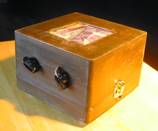
My first version of the Little Gem is a combo. Rather than use a crackerbox like Make, I picked up a little unfinished wooden box at the local craft store. Parts I picked up at a local electronics retailer, and Radio Shack (Rheostats are hard to find these days, the only place in my town to carry them was Radio Shack). The box is 6″ wide, 6″ deep, and 3.75″ tall. I bought a 4-inch 8-Ohm speaker that would fit nicely. I have no idea what the intended purpose of the speaker is, but I found it amongst other equipment for security systems. So it’s probably only supposed to be used to make an alarm wail. Fortunately, that pretty much is the range of my playing ability, so I didn’t expect any trouble.
As I mentioned in the previous post, the Make approach to the Little Gem uses a “prototype board” as the platform for the components. A prototype board is a little piece of perfboard that has traces glued to it in a useful pattern: 2 long columns down the center, and small rows connecting 2 perf holes at a time running perpendicular. One of the columns is wired to the positive terminal of the power source, the other to the negative. This way, any component that needs to go to ground (which is most of them) just needs to connect anywhere along the negative column. And anything needing power connects anywhere on the power column. Simple and logical. I never would have thought of it.
Another bit mentioned in the Make article was the use of a socket for the amp chip. Taken for granted by all the folks at Runoff Groove, I’m sure, but not something I would have thought of on my own. The socket is soldered to the board, and then the chip is just inserted– this way you don’t run the risk of cooking the chip while trying to solder connections to it. I also found the socket useful for another reason on my second build. More on that later.
Using the circuit diagrams and schematics provided by Make and Runoff Groove, and this perfboard layout drawing on flickr, I soldered all the connections, and gave it a quick test. Success! I had noise! Time to mount everything in the box. After initially screwing up the nice finish I had going on the box, I went for a more distressed look. It’s far easier to make something look like a piece of crap than it is to make something nice neat and shiny. Go figure. I drilled holes for the switch, input jack, and controls, and cut a ragged square out of the bottom for the speaker. I decided to mount the speaker to the bottom, and just turn the box over. At the time I was thinking that the larger mass of the box bottom might anchor the speaker better, and not create extra noise, but that’s probably just magical thinking.
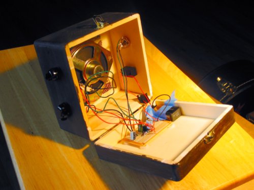
The pots are designed to mount to a sheet of metal or plastic, no more than 1/8″ thick. The box’s sides are 1/4″ inch thick. I used files and patience to ‘shallow out’ the box walls around the mounting holes, so that the pot and rheostat would stick out far enough for their threads to accept the nuts that anchor them down. Next time, I’ll make a control plate or something. This part was a pain in the ass.
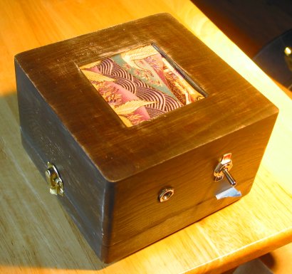
I stole a scrap of fabric from my wife’s collection scraps-for-quilts to mask the speaker through the hole. Pretty, isn’t it? I hot-glued plastic washers to the inside of the box to act as ‘standoffs’ to keep the perfboard and speaker from pressing directly against the walls. Then hotglued the perfboard and speaker down.
I had forgotten to buy a clip to secure the battery. So I taped it down. Wouldn’t want it rattling around in there, I’m a beginner at soldering, and some of those joints in there will probably snap easily. Chickenhead knobs and rubber feet added a nice finishing touch. Then it was time to play!
How did it sound? Pretty good, considering who built it, the cost of the components (~$25), and the fact it was powered by a 9 volt, of all things. But not great. For one thing, this design does not do clean. The only way I could get a clean tone was to turn the volume way down, where it could be drowned out by normal conversation. But distorted? Fuhgetaboutit! It sounded almost like my brother’s Pignose. I had accidentally dripped hot glue on the speaker cone as I was mounting it to the box– and thought I was out $4. But then I remembered how Link Wray used to claim he ‘d poke holes in his amp’s speakers with a pencil(Fender amps! the vandal!) to get that awesome distortion of his, so I figured hot glue couldn’t hurt too much. Maybe it colors the sound, who knows? I haven’t heard this particular speaker without hot glue on it, so… maybe it’s an improvement.
Here’s two .ogg files that will give you an idea of how it sounds (and an even better idea of how badly I play).
LGcomboWCM.ogg – this is as clean as I can get it. Not very.
LGcomboBB.ogg – this is with the gain all the way up. Rock out!
I decided that I’d never know how good or bad this amp design was without hearing it through proper speakers… and that led to my next build, coming in the next post.
I remember those little speakers you used. Amazing you were able to find any raw/project speakers in a Rat Shack these days. It was basically a Boombox Relacement speaker so it should work quite well in your Mini-Amp. I used to use them as tweeter/mids crossed over at 400 hz to a 8 inch woofer per box. Sounded good in that set-up.
Actually, I didn’t find them in a Radio Shack, but in a local electronics surplus store. Radio Shack carries less useful stuff everyday. The one in my town doesn’t even sell flux anymore. Only rosin-core solder. That just doesn’t cut it for soldering to pot cases. I can see how these speakers would be good tweeter/mids. Since they’re so cheap, I’ve been thinking about experimenting with damaging them to get certain types of distortion, like Link Wray and other early rockers who didn’t have the luxury of effects pedals.
hey there, I just completed my own “Little Gem”, but have found it to be so noisy (buzz sound) that it is practically useless. I am sure something is wonky, but I have check, double checked, and triple checked everything, and all is hooked up as it should be.
My LM386 doesn’t get super hot like I have read some other peoples have that had problems.
Did you have any problems like this?
One interesting thing to note, if I touch the outside of the nine volt battery, the noise almost disappears… strange
Right, well I figured out my noise issue, the input ground was not making a good connection.
With that resolved it sounds much cleaner, but volume levels are very very low, I hear the guitar itself louder then I hear the audio from the amp, even with gain and volume maxed out.
How loud is your setup? With both gain and volume maxed, is it quite loud?
Well, I am on a roll here. Post a problem, figure it out, post another problem, figure it out.
So my low volume was a result of an incorrectly wired input jack, DOH!
This thing is amazing, I cant believe the levels it can output, awesome!
Glad you got it sorted out. It’s amazing what a 9-volt will do, isn’t it?
Loose grounds are very common problems in these kind of projects. Seems I end up with one on almost everything I build. At least it’s easy to diagnose.
Congratulations on your successful build!
After playing with the lm386 for quite awhile on my breadboard I finally soldered up a prototype. I have added symmetrical clipping to the output with 1n34a germanium diodes which in my opinion helps the sound quite a bit, especially at full gain. I used a .1uf orange drop input cap and 10 ohm resistor and .047uf polyester film cap make up a high cut on the output. The bass is boosted by placing a .033uf poly cap and 10k resistor in series from the output back to pin 1 of the lm386. A 10uf electrolytic cap is run in series with a gain pot from pin one to pin eight to give an adjustable gain.
To reduce noise a 100uf electrolytic cap is used to smooth the 9v input voltage. A 47uf electrolytic cap is run from pin 7 to ground and a absolutely necessary 220uf cap is used to block the DC current riding on the output signal. Between these caps and the high cut filter my amp runs with an almost unnoticeable hum.
I run the amp to a closed back cabinet containing a 25 watt Celestion 12 inch speaker and in my opinion it was well worth the effort. After giving it a slight boost with my Big Muff Pi I have used it for recording a few tracks.
One thing of note is that this amp will chew up batteries when driving larger speakers and a well regulated power supply is recommended.
Take care…
Very interesting. Do you have a drawing or schematic? I’m able to make sense of most of your description, but I’m not too clear on some of your tweaks, and it sounds like you have a good version there. I’m sure the guys at runoffgroove.com would be interested in your mods as well.