Electric Kali: Progress. Also, Tim Knight is a Great Guy.

Making progress, slowly but surely. I’ve spent less time with this painting lately because I’m working on a new webcomic project, and Portal 2 came out. Seriously, buy this game. It’s excellent. More on the webcomic later, once the project is a little farther along.

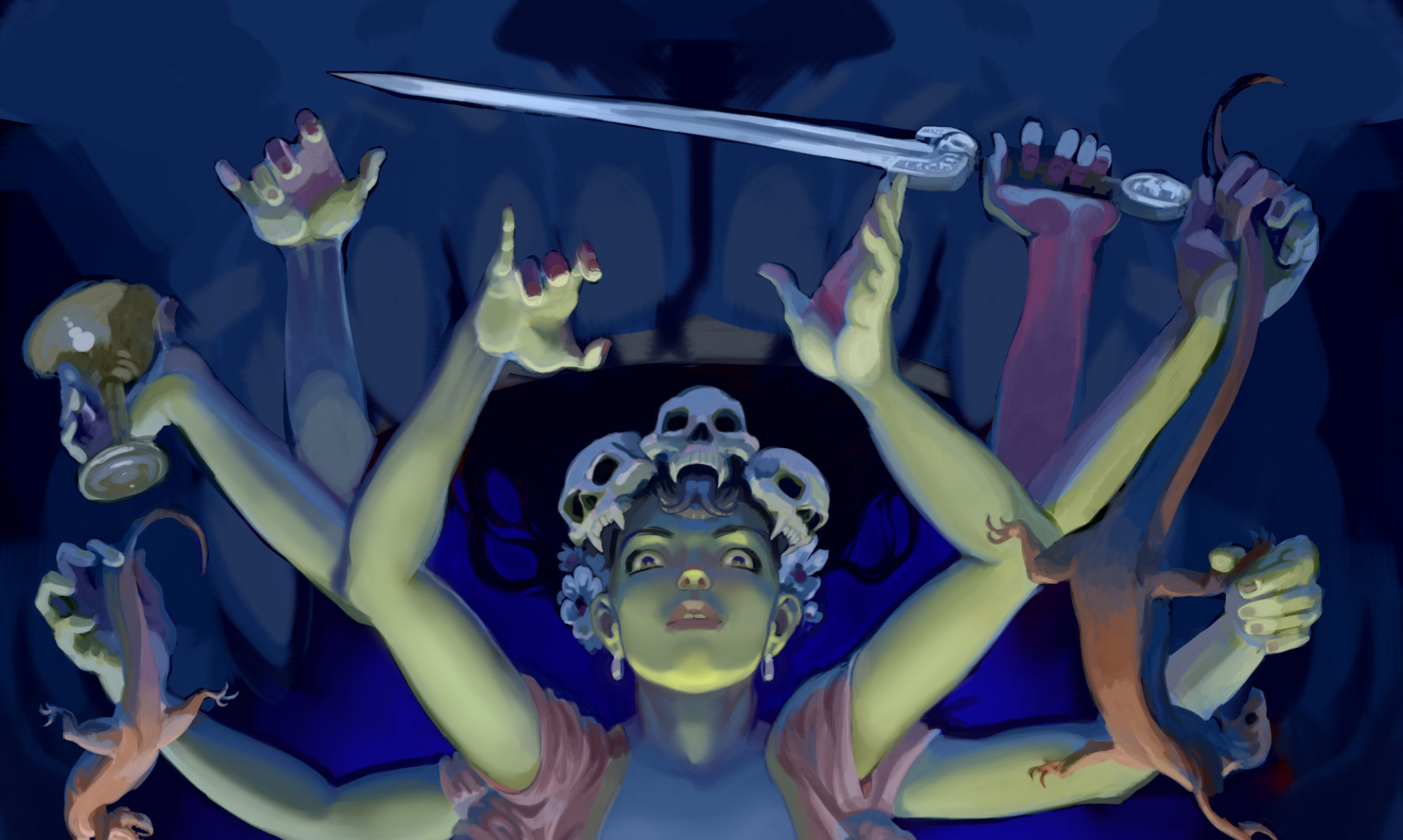
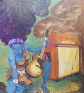
Here’s the final sketch for the painting. You can see that the background and some supporting details are missing or not fully realized. These will come as I paint. Mostly the sketch is to work out the basics. It was important to me that I choose the right guitar and amp combo for this image– it will matter little to most people, but I wanted to avoid just painting a generic “guitar.” I want to render something that a guitar fan will recognize and drool over.

After much hemming and hawing, I finally decided on a 50’s Gibson Les Paul Junior, and a 70’s red Marshall half-stack. The guitar is simple, pared-down to the essentials, but one with a very powerful voice. A true rock guitar. Marshall amps are of course the defacto symbol of rock; big, loud, screaming distortion. The red models they made in the 70’s are gorgeous, and I prefer to paint a big red amp than a boring black one. This guitar and amp combo represents power, aggression and fury quite well, I think.

It’s fairly easy to draw a generic guitar. But to draw a specific model recognizably is particularly difficult, at least for me. I was resigned to using a google image search for reference, but was discussing my choice of equipment with the inestimable Tim Knight, who had something much better in mind. Tim doesn’t have much of a web presence, which is a shame; he’s a cultural asset here in Salem, Oregon. Tim owns and operates Guitar Castle, a vintage guitar store downtown, and co-founded (but is no longer a partner of) Ranch Records, Salem’s best record store. Tim is a great musician; he played and recorded with John Fahey, is a member of the Hundred Dollar Jayhawks, the Nettles, and the Bohemian Enclave, which is his latest project. He helps organize local shows with local talent, and records and advises young up-and-comers. He’s friends with and sold guitars to many great musicians, and has countless great stories to tell.

I love Guitar Castle because there’s always a little bit of history on the racks there. While it is a vintage guitar store, Tim stocks guitars and amps for players, not collectors. For example, I bought a wonderful 1962 Fender Jaguar from him last year. It’s all original, but for one thing: a previous owner had stripped off the sunburst finish and sprayed it with clear nitro. This destroys its value as a collector’s item, but drops it neatly into my price range. A pre-CBS guitar that I can afford and sounds like a dream! (I’ll post more about this guitar some other time.) These kinds of deals make the store unique, and a great place to browse. Tim is also a painter, and his art is on the walls there. He paints scenes and portraits in a “naive” style, and his abstracts (my favorites) are colorful, thoughtful and emotive. (He also has a couple of my paintings hanging in the store. Thanks, Tim!)

When I told Tim the guitar and amp I had decided would be in Electric Kali, he laughed. “You mean like the ones in my basement?” he said. “Why don’t you shoot them for reference?” Tim Knight is a great guy. I came back a week later with my camera.

Tim poses the Les Paul Junior for me in front of Guitar Castle. 
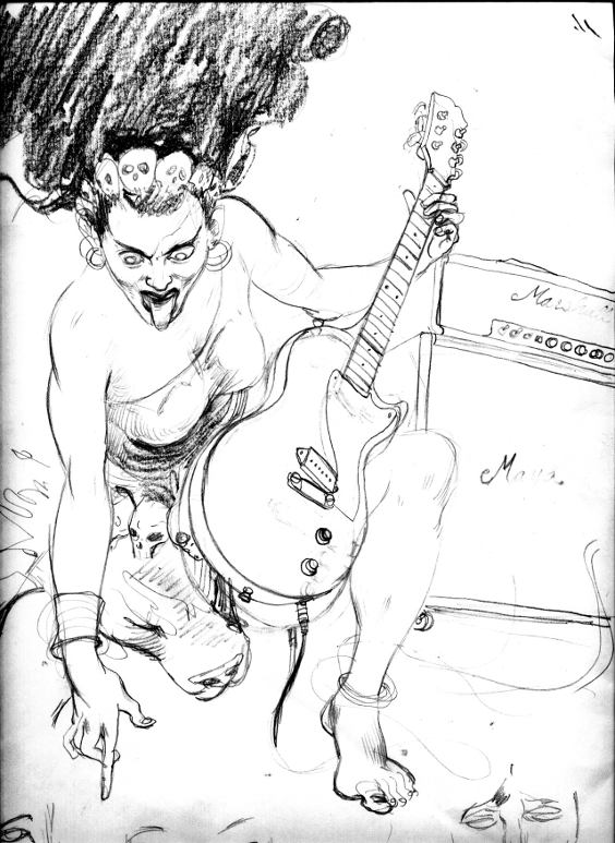
Here’s Tim with the Les Paul Junior. It’s no longer in the basement, it’s behind the counter, for sale at a bargain price.

Tim's red Marshall.  The racing stripes make it go faster. 
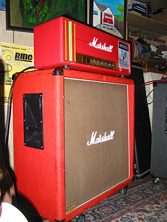
Tim’s red Marshall. Alas, this one is not for sale.

With the reference shot at just the angles I wanted, the sketch came together much faster than cobbling together images from the web. With the drawing done (more or less), I transferred it to a panel, and painted in the basic values using burnt umber and ultramarine. Now I’m roughing color in over the values, using glazes of varying opaqueness. The drawing is still visible a bit under the color, which will allow me to tighten up the detail once I’ve got the overall composition and color where I like it.

rough color going in

I like to work this way rather than make a color rough, because when I change my mind about a color and paint over it, the previous layers all build up to make a richer finish with more depth than if I just started with the right color first. More images to come as I continue to paint!

Little Gem part 5: Ruby

If I seem to be leaving info you want to know out, see if I’ve mentioned it already in the previous Little Gem posts, below. Or, ask away in the comments section.

The Ruby is a slight variation of the Little Gem design. The biggest difference is that it has a transister added to the circuit, placed to preserve the higher frequency signals, so the amp won’t sound as dark as the Little Gem. I built the previous Little Gems in order to gain enough experience to do the Ruby right; I had decided I would probably like the Ruby best, based on the write-ups and sound samples at www.runoffgroove.com.

For this build I splurged and bought a few cobalt drill bits, so that I would be able to drill a metal enclosure. I picked up a metal project box at the local electronics store. But I did not grab a punch, which is used to make an indentation to guide the drill bit when it starts to bore. This means that my holes were off center, or generally just not quite where I wanted them. I’ll have to get one for next time.

I also wanted to try to get the whole dc adapter + battery power situation to work this time. The only info I could find on how to do this was the stompbox wiring guide at Beavis Audio. I wasn’t making a stompbox, but I figured it couldn’t be too far from what I needed. And it wasn’t, except it took for granted that I would know which lugs was which on my dc adapter jack. It turns out I didn’t. But I’ll get to that. The stompbox layout also includes a led to let me know when it’s on, which means I didn’t need the little labeled washers, and can tell from far away if I’ve left it on.

The build went smoothly until it was time for me to connect the dc adapter jack. It has 3 lugs, 2 of which are connected to each other while nothing is plugged into the jack, but disconnected when your cable is plugged in.

Here’s where I got into trouble. I assumed that the center pin of the jack would be the positive pole, and the sleeve would be negative. After all, that’s how the mono plugs on our guitar cables work. Besides, wouldn’t it be a bad idea to have hot part of the plug exposed and therefore easiest to accidently ground, causing a short, or perhaps shocking someone?

This assumption is incorrect. It seems the most common way to wire dc plugs & jacks is called “center negative.” The pin in the center of the jack is negative, and the sleeve is positive. The reason for this is that the ‘switch’ that disconnects the 2 lugs I mentioned earlier when a plug is inserted into the jack is ‘thrown’ by being forced aside by the sleeve of the plug. This way the battery’s positive terminal is connected to the lug that is disconnected by the plug, and the plug’s sleeve provides power in its place. This way the battery won’t provide power when the wall-wart connected (which is what fried the first chip I had in my last Little Gem build).

Not knowing this, I connected the dc plug to the amplifier circuit with the center positive. When I plugged the amp into the wall, I ran 9 volts through the circuit backwards, which killed something in there. I couldn’t find exactly what I had destroyed– most likely the polarized capacitors, but perhaps also the transistor and chip. I had to toss the first build I made of the Ruby, as I had quite swiftly converted it to junk. I then struck out into the internets to discover what I have related above. I also realized I might have connected my transistor incorrectly as well, and ended up using the photo of a build Ruby on Runoffgroove combined with their board layout and schematics to get it right the second time.

It took two weeks for me to get over the disappointment and embarrassment of having wired my first attempt so wrongly, but after reading a great essay in Make magazine about the benefits of failure, I gave it another shot. And got it right on the second try. I still have to find some knobs for the box, but might just let that go– I’m considering all these mini-amps to be prototypes until I build one that I think is perfect enough, when I’ll build one to be pretty as well as great-sounding.

Here again are a couple of .ogg files demonstrating my poor skills and the amp’s sound:
Double Game – Kinda clean and quiet, as usual.
Woke Up Down – Gain way up. Nice and crunchy.

The Ruby does sound good. Certainly better than the Little Gem, which as I’ve said before, isn’t bad for 9 volts. The Ruby has just barely a bit more headroom, and a brighter sound than the Little Gem. I like it a lot, but am wondering about the Little Gem v.2, which uses 2 amplifier chips, splitting the signal load between themselves. The next amp I build will be that, but before I do, I have plans for some effects pedals…

Little Gem part 4: Head Building

So I had a cab all set; time to build a head version of the Little Gem and hook it up. Capacitors, resistors & the amplifier chip come several to a package, so I didn’t have to buy the whole parts list again, just a pot, rheostat, the polarized resistors, prototype board, knobs, switch and a box to put them all in. I picked up an inexpensive plastic ‘project box’ at the local electronics parts store. It’s about 5″ wide, 3″ deep and 3″ tall. I went with plastic because I didn’t have drill bits* capable of drilling through metal in any short amount of time. I also bought a dc plug, thinking I could run this head on an old 9 volt adapter I have left over from an effects pedal.

The build went smoothly, up to a point. It tested fine on the battery I’d installed, but when I plugged in the wall wart, I got nothing. Zilch. No sound, no nothing. I unplugged the wall wart, and went back to the battery. Still nothing.


See the gaping hole where I had to remove the DC plug?

Now, remember a few posts ago I mentioned another benefit of using sockets for your amplifier chip rather than soldering the chip directly? Here it is. Since I had a hunch I’d damaged my chip, and I had an extra chip (they come in packages of 3), I quickly swapped the chip out by prying it out of its socket with my thumbnail. Had I skimped on the socket, I would have had to desolder the whole thing (8 connections) running the risk of burning up the chip if it was ok on each joint, and then have to solder in a whole new chip.

With a fresh chip in place I tested the head with the battery, and it sounded out nice and loud. So obviously I’d burnt the chip when I plugged the amp into the wall. After a little research, it became obvious what I’d done. I’d bought a 2-lug dc plug. If you look at the stompbox wiring page at Beavis Audio, you’ll see that his dc plug has 3 lugs. This kind of plug doubles as a switch– when the wall wart plugs into this socket, it automatically switches off the flow of current from the battery. My 2-lug plug did not do this, and was in fact wired in series with the battery. So when I plugged it into the wall, I was running adapter current PLUS battery current, about 18 volts, through a chip rated for only 9. So, yeah, I burnt the chip. Luckily, they’re cheap.


These switches come with these little labeled washers. Useful for when you don’t want to wire a led to let you know when it’s on.

It’s a bit crowded inside, but only because I’ve been pretty sloppy with the wiring so far. Got to work on that.

Here are two samples of the Little Gem’s sound, in .ogg format. The cabinet is sounding great, nice and warm. Both are played on my partscaster, with the neck and bridge pickups mixed together.
Middle of the Road-ish – about as clean as it gets
Sunshine of Your Wub – Gain up about 3/4 of the way

* Actually, according to my old shop teacher, a ‘drill bit’ is the clamping part of the tool that holds the actual boring device, which should be called the ‘drill.’ The motor that turns the bit and drill assembly is, surprisingly enough, the ‘drill motor’. I grew up calling the drill a bit, the bit a chuck (the chuck is actually a specific part of the bit), and a drill motor a drill. That’s as may be, but every time I go the hardware store and ask for ‘drills,’ they take me to the ‘drill motors.’ Really, most of the time it doesn’t pay to be pedantic.

Little Gem part 3.2: Cab Building

As you can see from the drawings in the previous post, I had some idea of what I wanted. The consensus among audiophiles is that finger-jointed cabinets and amps are the best sounding. They also are difficult to build well, and my inability to saw a straight cut rules them out.

I also lack the most basic tool in a carpenter’s shop. My wife won’t let me buy a table saw, because in her line of work (medical) she sees many examples of table saw related accidents, and is convinced I would not keep my thumbs for very long should I be left in the same room as one of these diabolical machines. But evil though they may be, they are extremely useful, and I often have cause to curse my wife’s concern for my safety and low regard for my reserve of common sense. I am allowed a circular saw, though.

So, with limited tools and ability, I aimed for simple. Almost. Simplest would be to use butt-joints, but since I wasn’t going to cover the cabinet, butt joints would mean exposed end-grain, which I find ugly. So I set my circular saw to 45 degrees, and cut mitre joints. To get straight cuts with the table saw, I clamped one of my furring strips to the plank to act as a fence or guide for the blade. This helps, but it’s still difficult to get a truly straight cut. For this a mitre saw is better, but I don’t have one. After cutting the joint, I sanded and filed the edges to make them as smooth and straight as I could. Should use a plane for this, but don’t have one of those either. Rather than cut slots for biscuits, I screwed & glued the furring strips into the inside corners of the joints to make them stronger. Once together, the joints still showed gaps here and there– the cuts were not straight after all. I filled the gaps with wood filler.

I also used furring strips to support the baffle, and the panel on the back that would hold the connectors. Before mounting these parts I stained the wood– only to find that either I was using the wrong stain type or that my hemlock wasn’t too stain friendly– parts of the grain sucking stain up like a sponge, & other parts shedding it almost entirely, leaving a sort of tiger stripey feel, which I wasn’t really pleased with, but wasn’t ugly enough to cover with paint. After the stain dried, I sanded and gave it several coats of varnish, which I sanded & buffed– but only going up to medium grit buffing compound– which leaves the box with a semi-gloss or matte look. Basically, I just got bored buffing– it’s not a whole lot of fun, and with the poor stain, wasn’t aiming to make it look perfect or great, just ok was fine with me.

With the finishing out of the way, I cut the hole for the speaker in the baffle, using a jigsaw freehand. I actually got pretty close to circular, but it didn’t matter since I’d be hiding it behind my hard-won speaker cloth. I drilled holes for the t-nuts, and popped them into place. Then mounted the baffle to the furring strips with glue and wood screws. Every joint had glue and screws, the glue doing the real work, the screws really just there to hold the wood in place while the glue set. When the baffle had set, I mounted the speaker to it, with the face of the speaker pressing against the back of the baffle (t-nuts in front), to make use of the paper gasket on the face of the speaker. I used a jigsaw again to cut the hole for the connector panel, and mounted it with screws, and liquid nails, to reduce the possibility of getting a rattle or buzz caused by the speaker’s vibrations. I soldered the connectors to the speaker before I mounted the panel.

For the cover, I built a quick square frame using furring strips, glue and screws that was slightly (by about a 1/16″ – 1/8″ smaller than the opening at the front of the box. I made it smaller to allow space for the fabric to stretch around it. I stretched the fabric around the frame the same way you’d stretch a canvas for painting, but without pliers or a stretcher, because I needed to apply much less pressure– speaker fabric is very flexible, and anyway it didn’t have to be drum tight, it’s just there to hide the baffle & crooked hole cut in it. Since I had sized the frame just right, it fit snug in its place with no need to secure it. I screwed some plastic feet into the bottom (I had early decided which side was the bottom by determining which side was ugliest), and it was ready to test. I desoldered the leads running to the speaker in my first Little Gem, the combo, and connected them to the new cabinet to try it out.


What a difference a speaker makes! The same amp running through this larger speaker had only slightly more headroom, but much warmer, richer tone. And loud!

Now I had a cab, but had no head to run it. I put my combo back together, and got ready to build my first head, which I’ll describe in the next post…

Little Gem part 3.1: Cab planning

After I completed my first Little Gem build, I was still uncertain whether I liked the design or not. I had used an ultra-cheap, tiny speaker, and damaged it when installing it– so would it sound better with a better speaker? Could I squeeze out more headroom? (headroom is a term for being able to crank up an amp’s volume and still not distort the sound– useful for some players, but not for others. I prefer more headroom than your average heavy metal shredder, who might have little use of a clean tone.)

I decided that the only way to really be able to test the amp and to compare other modifications and mini-amp designs was to build a capable cab (speaker cabinet), and use it to test the designs I build. But how to build a cab?

I decided not to buy a cab, because the cheapest ones I could find ran $130+, and were butt-ugly. Surely I could build something better? But how? After checking out Shavano Music Online, DIY Guitarist, Duncan’s Amp Pages, and this page, I had a feel for what I needed to to, and that I was capable. I just had to figure out exactly what I wanted.

Speakers are a big deal. I remember as I was first shopping for amps discovering that the speakers that make good guitar amps are somewhat specialized. Modern speakers are fantastically well made– they can reproduce almost the full range of sounds humans are capable of hearing, with perfect clarity, and without ‘coloring’ or altering the sound of the music they reproduce. For guitar amps, this sucks.

Because guitar amps are supposed to create tone, not reproduce it.

One of the reasons that older, vintage amps are so prized, is that speaker technology 40 years ago sucked. Speakers created warmth and color because they were not as well designed as those of today, from a hi-fi perspective.

Beavis Audio has a project page on a pair of cabinets made from wooden trashcans (have I mentioned that Dano’s a freakin’ genius?). This is where I realized that I didn’t have to go all out and learn a bunch of difficult carpentry skills. It’s also where I learned about Weber Speakers. Weber makes speakers with all the design ‘flaws’ that make guitar amps sound great. They’ve got a huge selection, as well as amp & cab kits, and lots of info for anyone trying to understand how amps & speakers work, particularly regarding the tricky subject of impedance.

I ordered one of their 8″ ‘Signature’ Speakers. An alnico for $35. I quickly sketched up a design for a box, 15″ on a side and 7″ deep. Off to the hardware store! Cabs are usually covered in carpet or ‘tolex,’ a kind of leatherette. I didn’t want to bother with this, which meant I had to choose nicer-looking wood than is often used. I found 1×8 hemlock for an ok price. For the baffle (the panel that the speaker mounts to), I bought 3/4″ particle board, a 1/4 sheet. Now personally, I hate particle board. It’s heavy, ugly, and sucks moisture like a sponge. But it is flat, very flat. The Weber site warns against using a baffle that isn’t perfectly flat. They use steel baskets (the frame that supports the speaker cone) that are very thin, and bolting them to a slightly warped baffle can bend them out of shape, causing a ‘rub’ (where the coil rubs against the magnet), which can result in ugly noise, and eventually fire. This is bad. So, particle board for the baffle. Ugh. I grabbed T-nuts and matching screws for the mounting, a box of wood screws, and furring strips (strips of straight wood with a 3/4″ square cross-section.

At Radio Shack I picked up speaker connectors, a kind that accepts both banana plugs and bare wire. I had a scrap of plywood for a panel to hold the connectors. At a nearby fabric store I picked up a yard of speaker cloth, after a fair bit of trouble. The gals there didn’t know what ‘grille cloth’ was, and were apparently irked that a big ugly male had invaded their store looking to spend money, completely oblivious to their esoteric rituals and methods (I thought I was going to be kicked out when I produced a coupon at apparently the wrong time). It took a bit of talking before they finally sold me some speaker cloth, which is not as attractive as grille cloth, but would serve the purpose.

With all my materials in hand, it was time to come up with a plan, and build the damn thing, which I’ll cover in the next post.

Little Gem part 2: Combo

The Little Gem is very simple. It uses a tiny chip called “LM386-N” that does most of the work. A few capacitors help shape the tone, a potentiometer controls gain, and a rheostat for volume. With just a 9 volt battery, it’ll run an 8-Ohm cabinet– folks have bragged online that they’ve powered a 2×12 cab– that’s 2 twelve-inch speakers. I wouldn’t have thought it possible, until I built my own.

My first version of the Little Gem is a combo. Rather than use a crackerbox like Make, I picked up a little unfinished wooden box at the local craft store. Parts I picked up at a local electronics retailer, and Radio Shack (Rheostats are hard to find these days, the only place in my town to carry them was Radio Shack). The box is 6″ wide, 6″ deep, and 3.75″ tall. I bought a 4-inch 8-Ohm speaker that would fit nicely. I have no idea what the intended purpose of the speaker is, but I found it amongst other equipment for security systems. So it’s probably only supposed to be used to make an alarm wail. Fortunately, that pretty much is the range of my playing ability, so I didn’t expect any trouble.

As I mentioned in the previous post, the Make approach to the Little Gem uses a “prototype board” as the platform for the components. A prototype board is a little piece of perfboard that has traces glued to it in a useful pattern: 2 long columns down the center, and small rows connecting 2 perf holes at a time running perpendicular. One of the columns is wired to the positive terminal of the power source, the other to the negative. This way, any component that needs to go to ground (which is most of them) just needs to connect anywhere along the negative column. And anything needing power connects anywhere on the power column. Simple and logical. I never would have thought of it.

Another bit mentioned in the Make article was the use of a socket for the amp chip. Taken for granted by all the folks at Runoff Groove, I’m sure, but not something I would have thought of on my own. The socket is soldered to the board, and then the chip is just inserted– this way you don’t run the risk of cooking the chip while trying to solder connections to it. I also found the socket useful for another reason on my second build. More on that later.

Using the circuit diagrams and schematics provided by Make and Runoff Groove, and this perfboard layout drawing on flickr, I soldered all the connections, and gave it a quick test. Success! I had noise! Time to mount everything in the box. After initially screwing up the nice finish I had going on the box, I went for a more distressed look. It’s far easier to make something look like a piece of crap than it is to make something nice neat and shiny. Go figure. I drilled holes for the switch, input jack, and controls, and cut a ragged square out of the bottom for the speaker. I decided to mount the speaker to the bottom, and just turn the box over. At the time I was thinking that the larger mass of the box bottom might anchor the speaker better, and not create extra noise, but that’s probably just magical thinking.

The pots are designed to mount to a sheet of metal or plastic, no more than 1/8″ thick. The box’s sides are 1/4″ inch thick. I used files and patience to ‘shallow out’ the box walls around the mounting holes, so that the pot and rheostat would stick out far enough for their threads to accept the nuts that anchor them down. Next time, I’ll make a control plate or something. This part was a pain in the ass.

I stole a scrap of fabric from my wife’s collection scraps-for-quilts to mask the speaker through the hole. Pretty, isn’t it? I hot-glued plastic washers to the inside of the box to act as ‘standoffs’ to keep the perfboard and speaker from pressing directly against the walls. Then hotglued the perfboard and speaker down.

I had forgotten to buy a clip to secure the battery. So I taped it down. Wouldn’t want it rattling around in there, I’m a beginner at soldering, and some of those joints in there will probably snap easily. Chickenhead knobs and rubber feet added a nice finishing touch. Then it was time to play!

How did it sound? Pretty good, considering who built it, the cost of the components (~$25), and the fact it was powered by a 9 volt, of all things. But not great. For one thing, this design does not do clean. The only way I could get a clean tone was to turn the volume way down, where it could be drowned out by normal conversation. But distorted? Fuhgetaboutit! It sounded almost like my brother’s Pignose. I had accidentally dripped hot glue on the speaker cone as I was mounting it to the box– and thought I was out $4. But then I remembered how Link Wray used to claim he ‘d poke holes in his amp’s speakers with a pencil(Fender amps! the vandal!) to get that awesome distortion of his, so I figured hot glue couldn’t hurt too much. Maybe it colors the sound, who knows? I haven’t heard this particular speaker without hot glue on it, so… maybe it’s an improvement.

Here’s two .ogg files that will give you an idea of how it sounds (and an even better idea of how badly I play).

LGcomboWCM.ogg – this is as clean as I can get it. Not very.
LGcomboBB.ogg – this is with the gain all the way up. Rock out!

I decided that I’d never know how good or bad this amp design was without hearing it through proper speakers… and that led to my next build, coming in the next post.

Little Gem part 1

After I built my partscaster, I decided I needed to try something that didn’t involve hours of spraying laquer or buffing. Something that didn’t require me to be an obsessive neat-freak; a trait that runs counter to my nature. Why not effects pedals?

I found several sites online that had info to get me started. Beavis Audio was fascinating, but a bit over my head, as the last time I worked with electric circuits was back in high school (except for wiring my guitar, which was not really difficult, and did not require any understanding of what really goes on in those components). From Beavis Audio I found Runoff Groove, a treasure trove of schematics for various guitar effects projects, complete with sound samples and links to purchase kits of the designs. I was torn– which kit to buy? I couldn’t read schematics, and even the ‘perfboard layouts’ left me with more questions than answers– so I thought there was no way I’d be able to get started without a kit with very detailed instructions.

They have a project at Runoff Groove called the “Little Gem,” a tiny guitar amplifier that runs off a 9 volt battery. Their design assumes that it will be built as a ‘head’, that is, just the amplifier, with no speaker attached. Heads are connected to ‘cabs,’ or speaker cabinets (An amp with a built in speaker is called a ‘combo’). As I had no cabs lying around (I only owned a single amp– a combo), I figured I’d have to pass on the Little Gem, at least for a while.

But then volume 9 of Make Magazine arrived. In it, they had a HOWTO article on the Little Gem! They built it as a combo, using a cracker box as a housing! They lay out the circuit on a ‘prototyping board’ which makes interpreting the schematic much easier. The article, and accompanying materials I found online were complete enough to give me the cojones to try it out.

More about the Little Gem and about my first attempt to build one in the next post!